Content
In a refinery or petrochemical plant, a flare system stands as the last line of defense for safety and environmental compliance. When process upsets, maintenance shutdowns, or emergency relief events occur, flammable gases must be disposed of quickly and safely—not released into the atmosphere. An industrial flare system does exactly that: it collects, transports, and burns excess hydrocarbon gases at high temperature, converting them into less harmful combustion products. Here is how it works, beginning with the fundamental principle and moving through each stage of operation.
An industrial flare operates on the principle of high-temperature oxidation. Combustible gases—primarily hydrocarbons, volatile organic compounds (VOCs), and sometimes hydrogen or carbon monoxide—are mixed with air (or oxygen) and ignited. The resulting flame maintains a temperature typically between 1,000 °C and 1,200 °C, which ensures that at least 98 % of the hydrocarbons are converted into carbon dioxide (CO₂) and water (H₂O). This process effectively destroys the harmful components that would otherwise pose fire, explosion, or toxicity risks.
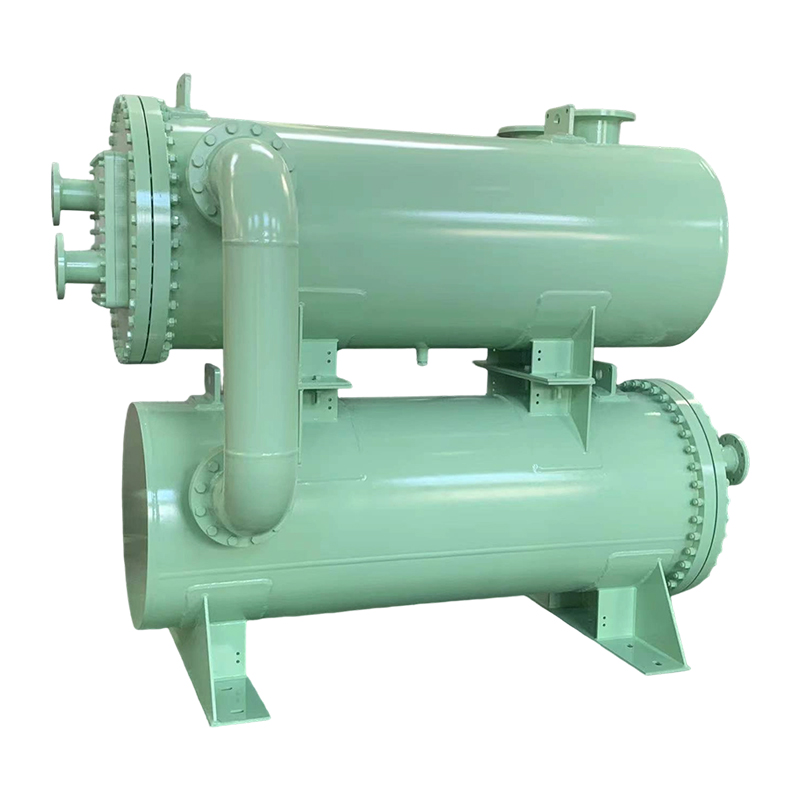
Before any flame appears, the flare system must gather gases from multiple sources across a facility. Relief valves, blowdown valves, and vent lines feed into a main collection header—a large-diameter pipe that runs to the flare stack. Along the way, a knockout drum separates any liquid droplets (condensed hydrocarbons, water, or entrained liquids) from the gas stream. Removing liquid is critical: droplets can cause flame instability, smoking, and even damage to the flare tip. The knockout drum typically uses gravity or a mist eliminator pad to achieve separation. Clean, dry gas then continues to the flare stack.
Between the knockout drum and the flare tip, a gas seal prevents air from flowing backward into the collection header. Without a seal, air could mix with combustible gas inside the pipe, creating an explosive mixture. A purge gas—usually nitrogen or natural gas—continuously flows through the system to maintain a slight positive pressure and ensure no backflow occurs. This small constant flow is carefully controlled to minimize waste while maintaining safety.
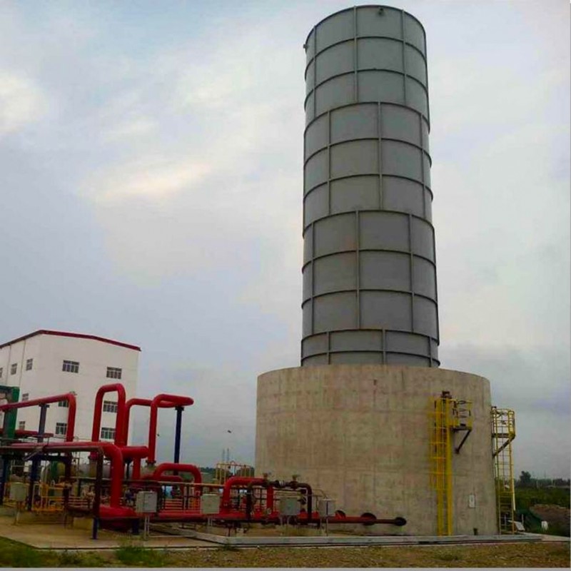
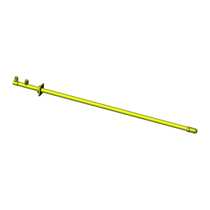
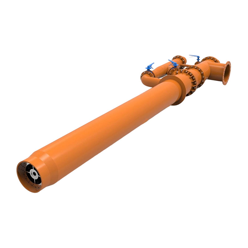
The flare tip is the visible end of the system, where combustion takes place. It is designed to mix gas with air efficiently and sustain a stable flame. An array of pilot burners, fueled by a small continuous supply of natural gas or propane, maintains a permanent ignition source. When the main gas flow arrives, the pilot flame instantly ignites it. Modern systems use a flame-front ignition system or direct spark ignition to reignite pilots automatically if they go out.
Complete combustion requires three elements: fuel, oxygen, and temperature. The flare tip geometry and a method called “steam-assisted” or “air-assisted” flaring enhance mixing. In steam-assisted flares, high-pressure steam is injected into the gas stream just below the tip. This draws in ambient air and creates turbulence, breaking the gas into smaller droplets and improving the oxygen-to-fuel contact. For smokeless operation, especially with heavy hydrocarbons, steam injection suppresses soot formation by promoting water‑gas shift reactions. Air-assisted flares use a fan or blower to supply combustion air directly.
| Assistance Method | Purpose | Typical Soot Reduction | Energy Consumption |
|---|---|---|---|
| None (open pipe) | Simple, low cost | 0 – minimal | None |
| Steam assistance | Improves mixing, suppresses soot | 90 – 99 % | Moderate (steam generation) |
| Air assistance | Forces air into flame zone | 80 – 95 % | Low to moderate (fan power) |
| High-pressure gas injection | Creates turbulence, reduces smoke | 70 – 90 % | Low (compressor duty) |
The choice of assistance method depends on gas composition, flow rate, and local environmental regulations. For example, a refinery processing heavy crude may rely on steam assistance to meet opacity limits, while a gas plant with dry natural gas might operate a simple open-pipe flare.
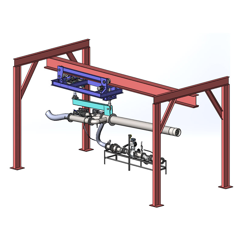
To ensure reliable and compliant flaring, many industrial operators turn to a complete 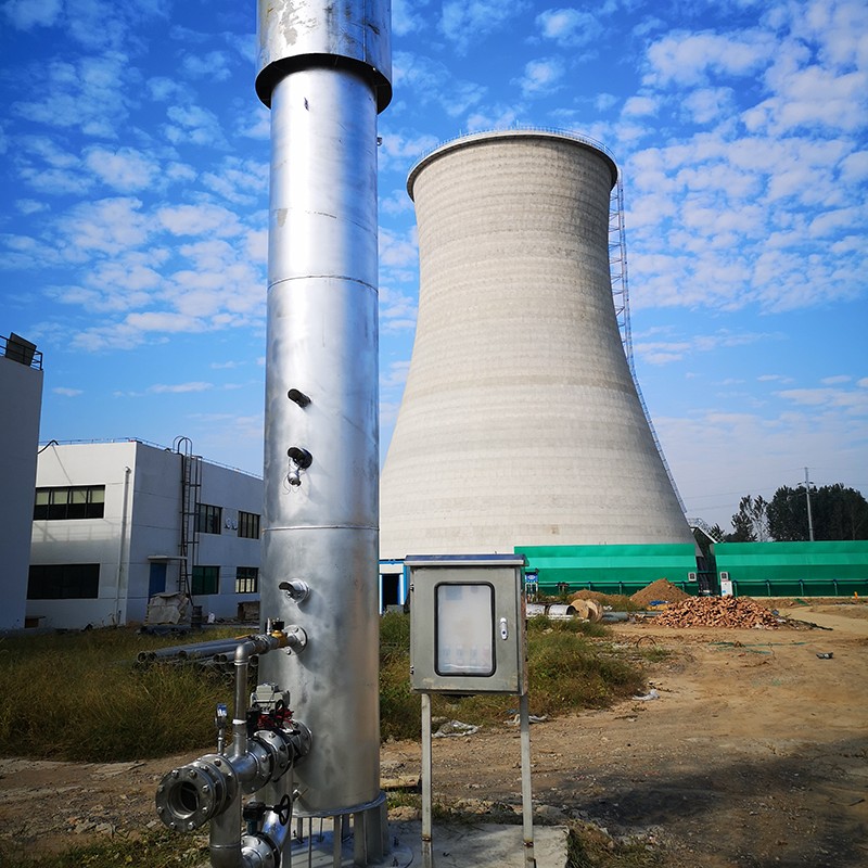 GeneralFlame Complete Flare System for Industrial SafetyExplore GeneralFlame’s integrated flare system, which incorporates essential supporting components beyond the tip to deliver safe pressure relief, environmental compliance, and stable production in petrochemical and coal chemical plants.View Product → that integrates these components into a unified solution. General Flame’s flare systems include knockout drums, gas seals, pilot burners, and control panels designed for long service life and low maintenance.
Beyond the tip, several supporting parts ensure safe and efficient operation:
Flare systems are categorized by configuration and application. The three most common types are:
The effectiveness of a flare system directly influences plant safety and regulatory compliance. Poor mixing can lead to visible smoking, which violates emissions permits. Incomplete combustion leaves unburned hydrocarbons, methane, and VOCs in the atmosphere, contributing to smog and greenhouse gas emissions. A properly engineered flare system achieves destruction and removal efficiency (DRE) of at least 98 %, and often 99.9 % for hazardous organic compounds.
Another critical factor is the turn‑down ratio—the ability to operate over a wide range of gas flow rates. During a major emergency, the system must handle the full relief load, while under normal conditions it might only see pilot and purge flow. Flare designs that include multiple tip stages or adjustable steam injection can maintain stable, low‑smoke combustion across the entire range.
Environmental regulations in many jurisdictions now require continuous monitoring of pilot flame presence, visible emissions, and sometimes net heating value of the flared gas. Newer flare controllers use flowmeters, gas chromatographs, and infrared cameras to adjust assistance in real time, reducing steam or air consumption while maintaining compliance. For additional insights on proper system selection, readers can review our detailed article on flare system components, types, and function.
An industrial flare system works by collecting waste hydrocarbon gases, removing liquids, and burning them in a controlled high‑temperature flame that achieves near‑complete combustion. The choice of tip design, assistance method, and supporting components determines whether the system meets safety, environmental, and operational requirements. Whether you are planning a new installation or upgrading an existing flare, understanding these working principles helps you make informed decisions about reliability, emissions, and long‑term cost.


 OEM/ODM High-Performance Combustion & Thermal Equipment Manufacturers
 English
 русский
 Français
 Español
 عربى
عربى