Content
A flare system is an industrial safety and combustion device used primarily in the oil and gas, petrochemical, and refining industries to safely dispose of unwanted or excess hydrocarbon gases by burning them in a controlled manner. Rather than releasing toxic or flammable gases directly into the atmosphere, a flare system routes them to a combustion point — typically an elevated or ground-level flare tip — where they are ignited and converted into less harmful combustion byproducts, primarily carbon dioxide (CO₂) and water vapor.
In simple terms, a flare system is the last line of defense against uncontrolled gas release. It is not a normal operating process but a critical emergency and pressure-relief mechanism that ensures plant safety, regulatory compliance, and environmental protection. Globally, flare systems burn an estimated 140–150 billion cubic meters of natural gas per year, according to the World Bank's Global Gas Flaring Reduction Partnership (GGFR).
Flare systems serve several distinct but interrelated purposes in industrial operations:
A well-designed flare system achieves a combustion efficiency of 98–99.9%, meaning nearly all hydrocarbons are destroyed rather than emitted as uncombusted volatile organic compounds (VOCs).
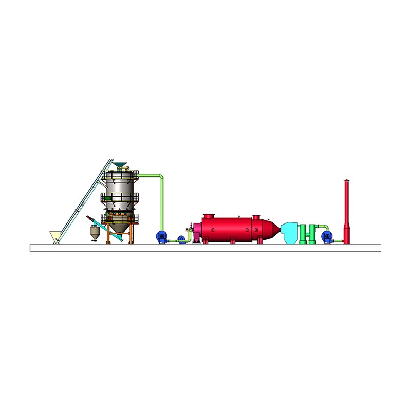
A complete industrial flare system is not just a single burning torch — it is an integrated network of equipment working together. The key components include:
The flare header is a network of pipes that collects relief gas from multiple sources across a facility — pressure relief valves, blowdown valves, and control valve bypasses — and routes them to a central knockout drum and then to the flare stack. Header sizing is critical: undersized piping creates dangerous back-pressure that can prevent relief valves from opening at the correct set pressure.
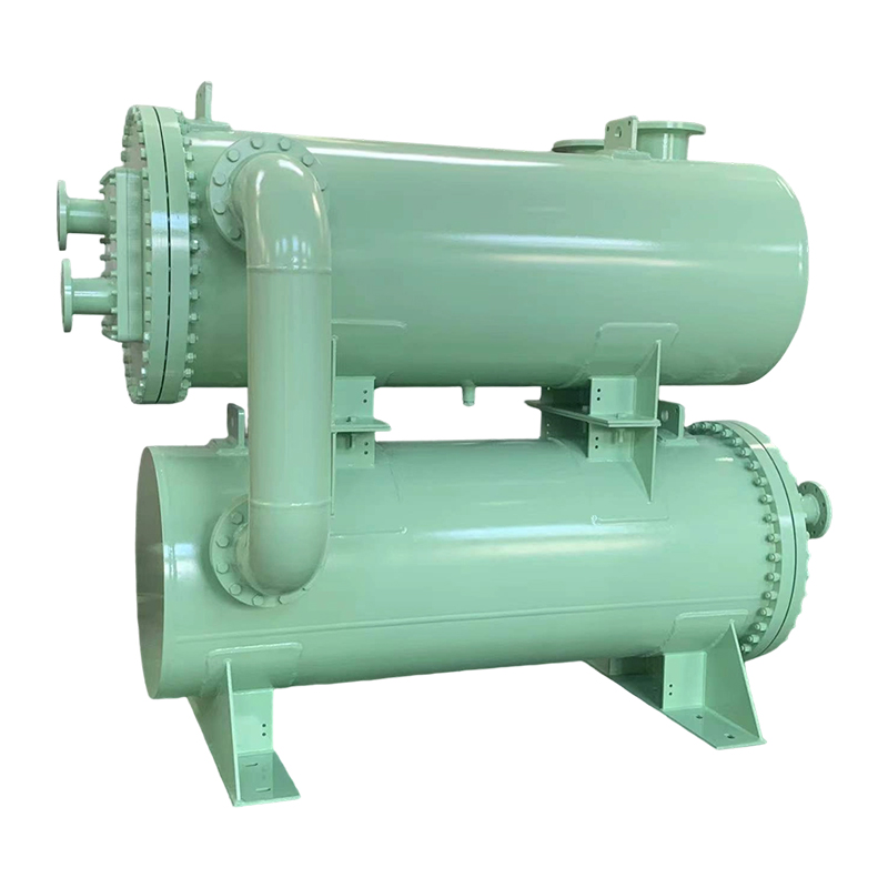
Before gas reaches the flare tip, it passes through a knockout drum (also called a flare knockout vessel or liquid seal drum). This vessel separates entrained liquids from the gas stream. Liquids entering a flare tip can cause dangerous "flare raining" — burning liquid droplets falling from the stack — and can damage the tip or cause explosions. The knockout drum is a non-negotiable safety feature in any properly engineered flare system.
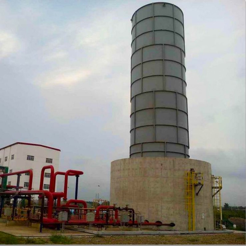
The flare stack is the structural element that elevates the flare tip to a safe height above grade level. Stack heights typically range from 30 to over 150 meters, depending on the facility size, the heat radiation limits required at grade level, and local regulatory requirements. Offshore platforms often use horizontally extended flare booms instead of vertical stacks to direct the flame away from the platform structure.
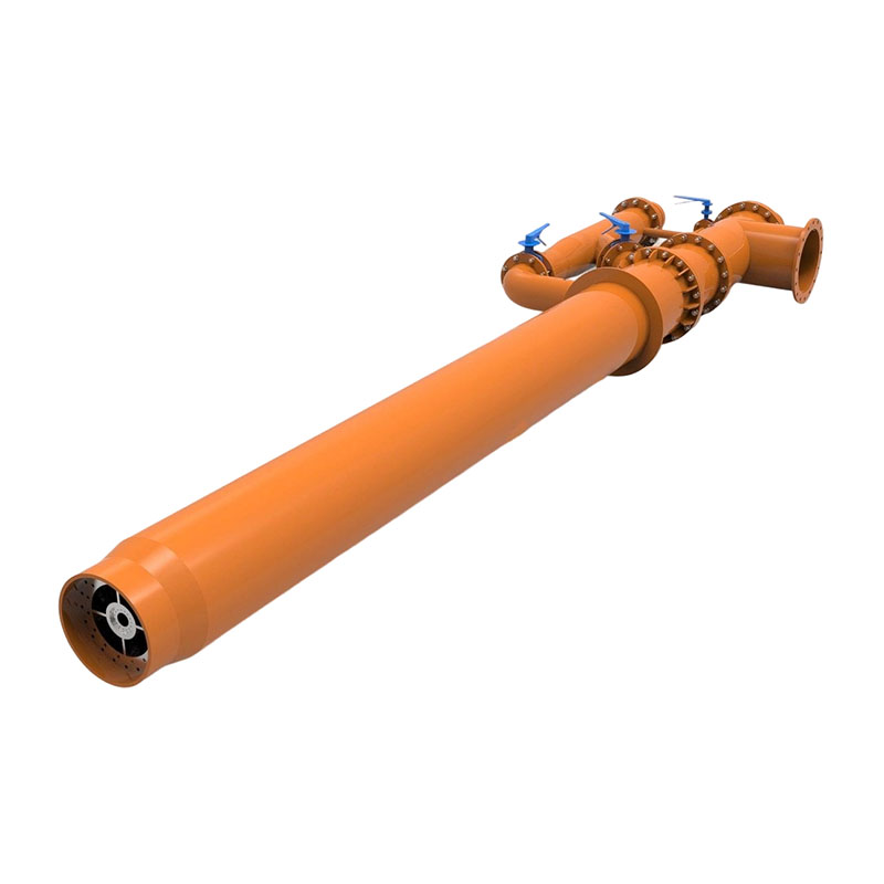
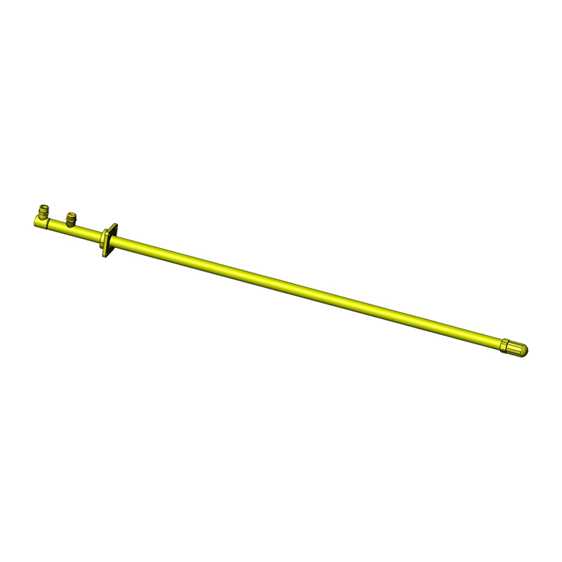
The flare tip is the combustion device at the top of the stack where gas is ignited and burned. Modern flare tips are engineered for specific flow rates and gas compositions, and include features such as:
Pilot burners maintain a constant small flame at the flare tip at all times, ensuring that any gas released — even unexpectedly at 3 AM — ignites immediately. Most modern systems use high-energy spark ignition or flame front generator (FFG) systems to re-light pilots remotely if they are extinguished by wind or rain. A flare system with an unlit pilot is a serious safety violation.
A continuous flow of inert or fuel gas (nitrogen or natural gas) is injected into the flare header to prevent air from migrating back into the system and creating a potentially explosive air-gas mixture inside the piping. This "purge gas" flow is one of the ongoing operational costs of maintaining a flare system and typically runs at a rate of 0.1 to 1.0 m/s at the flare tip exit.
Installed at the base of the stack or within the header, water seals and molecular seals serve as secondary barriers against air ingress and also function as pressure relief check valves. A water seal drum maintains a water column (typically 150–300 mm deep) that gas must bubble through, providing both a seal and a visual indicator of gas flow rates during operations.
Flare systems are classified by their physical configuration and the method used to achieve smokeless, efficient combustion. Each type is suited to different operational and environmental conditions.
| Flare Type | Configuration | Typical Application | Key Advantage |
|---|---|---|---|
| Elevated Flare | Vertical stack, tip at height | Refineries, petrochemical plants | Disperses heat and noise; handles large flows |
| Ground Flare | Enclosed or open burners at grade | LNG terminals, gas plants | Low noise, low luminosity, smokeless |
| Offshore Flare Boom | Horizontal arm extending from platform | Offshore oil and gas platforms | Keeps flame away from structure |
| Steam-Assisted Flare | Steam injected at tip | Facilities with available steam | Smokeless combustion of heavy gases |
| Air-Assisted Flare | Forced air blower at base | Remote sites without steam | Smokeless without steam infrastructure |
| Candlestick Flare | Simple unassisted vertical pipe | Low-flow or backup flares | Low cost, minimal maintenance |
Understanding the operational sequence of a flare system clarifies why each component exists and matters:
Flare systems must be engineered to internationally recognized standards. The two most authoritative documents governing flare system design are:
In the United States, the EPA's 40 CFR Part 60 and Part 63 regulations govern flare combustion efficiency requirements and monitoring obligations. Under these rules, flares must maintain a net heating value (NHV) in the combustion zone of at least 270 BTU/scf and a maximum tip velocity below a defined threshold to ensure stable, efficient combustion.
The EU Industrial Emissions Directive (IED 2010/75/EU) and associated Best Available Techniques (BAT) conclusions similarly require facilities to minimize flaring and demonstrate continuous combustion efficiency monitoring at major installations.
While flare systems are far safer than uncontrolled gas venting, they are not without environmental impact. Key concerns include:
When combustion is complete, flaring produces CO₂ — a greenhouse gas. However, incomplete combustion generates methane (CH₄), which has a global warming potential approximately 84 times greater than CO₂ over a 20-year period. At an assumed combustion efficiency of 98%, a flare venting 1,000 kg/hour of methane still emits roughly 20 kg/hour of uncombusted methane — a meaningful climate impact at scale.
Flaring heavy hydrocarbon gases without sufficient air or steam assistance produces black smoke — soot particles (PM2.5 and PM10) that represent both an air quality issue and a regulatory violation. This is why smokeless flaring requirements are enforced at most modern industrial facilities, typically requiring smokeless operation up to at least 50% of the design flaring rate.
The World Bank's "Zero Routine Flaring by 2030" initiative, launched in 2015, has attracted endorsements from over 90 governments and oil companies. The initiative targets the elimination of "routine flaring" — continuous flaring of associated gas during oil production simply because no infrastructure exists to capture it. As of recent reporting, global flaring volumes remain stubbornly high at approximately 144 billion cubic meters per year, underscoring the difficulty of the transition.
The most effective way to reduce flaring is not to improve the flare itself, but to avoid sending gas to the flare in the first place. Flare gas recovery (FGR) systems capture low-pressure gas from the flare header before it reaches the knockout drum and re-compress it for use as fuel gas, or reintroduce it into the process. A well-designed FGR system can reduce routine flaring by 70–90%.
Typical FGR system components include:
For large refineries, the economic case for FGR is strong: recovering just 1 million standard cubic feet per day (MMSCFD) of gas that would otherwise be flared can represent annual savings of over $1 million at natural gas prices of $3–4/MMBtu, while simultaneously reducing emissions and regulatory liability.
Modern flare systems are not passive infrastructure — they are actively monitored through instrumentation and control systems. Key monitoring elements include:
Under EPA Subpart Ja (for petroleum refineries), facilities are required to install continuous parameter monitoring systems (CPMS) and submit quarterly compliance reports demonstrating that flare combustion efficiency standards were maintained throughout each operating period.
Even well-designed flare systems can experience operational issues. Understanding the most common failure modes helps operators and engineers anticipate and prevent them:
| Problem | Root Cause | Consequence | Mitigation |
|---|---|---|---|
| Pilot flame extinguishment | High wind, rain, or low pilot gas pressure | Unlit flaring — raw gas release | Auto-ignition systems, wind shields |
| Flare tip burnback | Low gas flow, flame drawn into tip | Tip damage or destruction | Adequate purge gas flow, tip design |
| Liquid carryover | Knockout drum undersized or failed | Burning liquid rain, tip damage | Correct KO drum sizing, level control |
| Excessive smoking | Insufficient steam/air assist | Regulatory violation, PM emissions | Increase assist flow, tip maintenance |
| Header overpressure | Undersized piping or blocked path | Back-pressure prevents PRV opening | API 521 hydraulic analysis, inspections |
While flare systems are most closely associated with the oil and gas industry, they are used across a broad range of industrial sectors wherever flammable or hazardous gases are produced:
The industrial world is under growing pressure to minimize flaring through both technological innovation and regulatory tightening. Key trends shaping the future of flare systems include:
Next-generation flare tips with improved internal mixing geometry can achieve smokeless combustion at flows up to 90% of design capacity without steam assist, reducing operating costs and auxiliary emissions. Manufacturers such as John Zink Hamworthy and Zeeco offer patented tip designs with significantly improved combustion efficiency and reduced noise profiles.
VIIRS (Visible Infrared Imaging Radiometer Suite) satellite sensors, operated by NOAA and NASA, now detect and quantify flaring events globally with a detection threshold of approximately 1 MW of radiative power. This capability means regulators and investors can independently verify facility-level flaring data, increasing accountability beyond self-reported figures.
Several oil-producing regions including the Permian Basin (Texas), the Vaca Muerta (Argentina), and the North Sea have introduced progressively tighter flaring limits or outright bans on routine flaring for new projects. Companies that fail to meet these requirements face production curtailments, financial penalties, or loss of operating licenses — creating a strong economic incentive to invest in gas capture infrastructure over continued flaring.


 OEM/ODM High-Performance Combustion & Thermal Equipment Manufacturers
 English
 русский
 Français
 Español
 عربى
عربى