Content
A grate cooler is a critical piece of equipment in cement manufacturing that rapidly cools clinker discharged from the rotary kiln — from temperatures exceeding 1,400°C down to below 100°C — while simultaneously recovering thermal energy to preheat combustion air. Without an efficient grate cooler, clinker quality degrades, fuel consumption rises, and downstream handling equipment suffers accelerated wear.
Modern grate coolers recover up to 75% of the heat content in hot clinker and return it to the kiln system as secondary and tertiary air, directly reducing specific heat consumption by 80–120 kcal/kg clinker. This makes the grate cooler one of the highest-impact components in the entire cement production line from both a quality and energy efficiency standpoint.
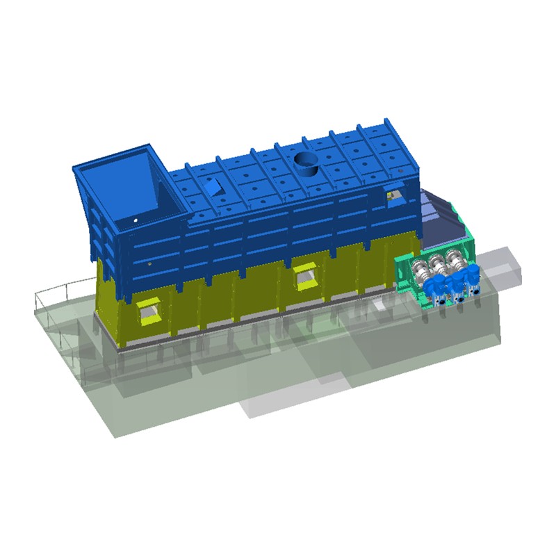
The grate cooler is positioned immediately at the discharge end of the rotary kiln. As red-hot clinker nodules exit the kiln at temperatures of 1,350–1,450°C, they fall onto a moving perforated grate through which large volumes of ambient air are forced upward by high-pressure fans positioned beneath each grate compartment.
The cooler serves three simultaneous functions in the cement production process:
The hot air recovered from the cooler is channeled in two streams: secondary air enters the rotary kiln burner directly (typically 900–1,050°C), while tertiary air is ducted to the calciner in 5-stage or 6-stage preheater systems (typically 850–950°C). Any excess hot air that cannot be used productively is vented through a cooler exhaust stack, often after passing through a waste heat recovery boiler for power generation.
Understanding grate cooler operation in sequence helps clarify why design details matter so significantly to performance outcomes.
The airflow management beneath the grate is critical. Modern grate coolers use individually controlled compartment fans with variable frequency drives (VFDs) and pressure sensors to optimize air distribution across the clinker bed, preventing "red rivers" — channels of insufficiently cooled clinker that bypass proper air contact.
Grate cooler technology has evolved through several distinct generations, each addressing specific limitations of its predecessor. The generation classification is widely used in the cement industry to describe the technology level of an installation.
The earliest grate coolers used a single-speed reciprocating grate with fixed air distribution. Heat recovery efficiency was low — typically 55–62% — and the equipment suffered from severe wear due to clinker falling through grate gaps (called "snowman formation" at the inlet and "red rivers" at the cooler discharge). These units required frequent maintenance stops.
Second-generation designs introduced multiple independently controlled air compartments beneath the grate. Variable air volume control improved heat recovery to 65–70%. However, mechanical wear of grate plates remained a significant operational cost, and clinker "fall-through" continued to be a problem.
The key innovation of third-generation coolers is the separation of the inlet zone from the moving grate. A fixed static inlet section with aeration chambers prevents clinker from piling unevenly and eliminates the mechanical wear in the highest-temperature zone. Heat recovery efficiency improved to 70–75%. Examples include the FLSmidth Cross-Bar Cooler and the thyssenkrupp Polytrack.
The newest generation eliminates traditional reciprocating grate plates entirely in favor of roller-based transport systems (such as the KHD Pyrofloor or FLSmidth SF Cross-Bar Cooler). Clinker is transported by rollers rather than sliding plate-to-plate, dramatically reducing wear and maintenance. These systems achieve heat recovery efficiencies exceeding 75–78% and specific cooling air consumption below 1.8 Nm³/kg clinker.
Evaluating grate cooler performance requires tracking several interdependent parameters. The table below shows typical benchmark ranges for a well-operating modern grate cooler:
| Parameter | Typical Range | Best-in-Class Target |
|---|---|---|
| Clinker inlet temperature | 1,350–1,450°C | — |
| Clinker outlet temperature | 65–150°C | <65°C (ambient +65°C) |
| Heat recovery efficiency | 68–75% | >75% |
| Specific cooling air volume | 1.8–2.5 Nm³/kg clinker | <1.8 Nm³/kg clinker |
| Secondary air temperature | 900–1,050°C | >1,000°C |
| Tertiary air temperature | 850–950°C | >900°C |
| Specific heat consumption saved | 80–120 kcal/kg clinker | — |
| Grate loading (specific throughput) | 35–45 t/d/m² | Up to 50 t/d/m² |
| Fan power consumption | 3.5–6 kWh/t clinker | <4 kWh/t clinker |
Each component in the grate cooler system plays a defined role. Understanding the function of each part is essential for maintenance planning and troubleshooting.
Grate plates are the perforated or slotted cast alloy components that form the clinker-bearing surface. They must withstand temperatures up to 1,200°C at the inlet, continuous mechanical abrasion from moving clinker, and thermal cycling stress. Modern grate plates are made from heat-resistant alloy steels (typically containing chromium, nickel, and molybdenum) and are designed for individual replacement without full grate shutdown. Grate plate wear is the single largest maintenance cost in cooler operation, often accounting for 40–60% of total cooler maintenance expenditure.
Beneath the grate, the housing is divided into multiple air compartments — typically 8 to 16 sections depending on cooler size. Each compartment has a dedicated centrifugal fan, damper, and pressure measurement point. Variable frequency drives on each fan motor allow precise airflow control matched to the clinker bed depth and temperature profile detected by thermocouples. Modern systems use automated process control loops to continuously adjust fan speed.
The reciprocating grate is driven by hydraulic cylinders or electromechanical drives. The stroke frequency and length are adjustable to control clinker bed depth and residence time. In modern CrossBar and roller-type coolers, individual row drives allow each grate section to move at a different speed, enabling optimized clinker distribution without the avalanche effects seen in older uniform-drive designs.
Positioned at the cooler discharge, the clinker crusher reduces oversized nodules and agglomerates to below 25 mm for safe handling by downstream conveyors. The two main types are the roller crusher (preferred for its low dust generation and adjustable gap) and the hammer crusher (higher throughput but greater wear and dust). Roller crushers have largely replaced hammer types in new installations due to lower maintenance requirements.
The cooler walls, particularly in the hot zone (first 8–12 meters), are lined with high-alumina or silicon carbide refractory bricks to protect the steel shell from radiant heat and hot gas erosion. The bull nose — a refractory shelf separating the kiln flame zone from the cooler inlet — is a critical wear point that requires inspection every major shutdown.
Operational problems in grate coolers follow recognizable patterns. Early diagnosis and targeted corrective action are key to minimizing production losses and equipment damage.
Snowman formation occurs when liquid or semi-liquid clinker accumulates and solidifies on the cooler inlet section, forming large irregular masses that restrict kiln discharge and airflow. It is typically caused by excessively liquid clinker (high liquid phase content above 28%), kiln coating falls, or low clinker discharge rates. Resolution involves adjusting raw mix composition (reducing Fe₂O₃ and Al₂O₃), optimizing kiln operation to avoid coating collapses, and using water cannons or pneumatic hammers to break accumulated deposits.
Red rivers are channels of insufficiently cooled, glowing clinker that bypass the normal airflow and reach the cooler discharge at temperatures exceeding 400–600°C. They damage downstream equipment and indicate poor air distribution. Causes include uneven clinker bed depth, damaged or blocked grate plates, or under-pressurized air compartments. The fix involves rebalancing compartment air volumes, replacing damaged grate plates, and improving clinker distribution at the inlet.
Fine clinker particles falling through grate plate perforations accumulate in the undergrate compartments, reducing fan efficiency and creating a fire hazard. In severe cases, undergrate clinker buildup can completely block air flow to one or more compartments, causing local overheating. Regular purging of undergrate hoppers, optimized grate plate perforation geometry, and maintaining appropriate bed depth reduce fall-through rates.
Excessive grate plate wear is often caused by abrasive fine clinker, high inlet temperatures, or improper grate speed (too slow causes deep bed and high thermal load; too fast causes thin bed and direct clinker-to-plate impact). Using higher-alloy plates in the inlet zone, monitoring wear rates through scheduled inspection, and maintaining optimal bed depth of 400–600 mm all extend plate life.
If more air is blown through the clinker than can be usefully recovered as secondary or tertiary air, the excess vents to atmosphere at elevated temperatures — typically above 250°C — representing a direct heat loss and a filter bag protection concern. The solution involves installing a waste heat recovery (WHR) boiler on the cooler vent to generate electricity, or reducing total cooling air volume while improving air distribution efficiency.
The grate cooler is not the only clinker cooling technology, though it is by far the dominant design in modern cement plants. Understanding the alternatives clarifies why the grate cooler became the industry standard.
| Feature | Grate Cooler | Rotary Cooler | Planetary Cooler |
|---|---|---|---|
| Heat recovery efficiency | 70–78% | 55–65% | 60–68% |
| Clinker outlet temperature | <100°C | 150–250°C | 100–200°C |
| Clinker capacity | Up to 12,000 t/d | Up to 3,000 t/d | Up to 3,500 t/d |
| Tertiary air extraction | Easily integrated | Difficult | Not possible |
| Maintenance complexity | Moderate–High | Low–Moderate | Moderate |
| Suitability for WHR power generation | Excellent | Poor | Limited |
| Industry adoption (new plants) | Dominant (>95%) | Rare (legacy only) | Rare (legacy only) |
Rotary coolers and planetary coolers dominated cement plants built before 1980 but are no longer installed in new plants. Their inability to support tertiary air ducting for precalciner systems — which are standard in all modern large kilns — and their lower heat recovery make them economically inferior. Most plants with rotary or planetary coolers have since upgraded to grate coolers as part of capacity and efficiency modernization projects.
For plants operating older generation coolers or underperforming systems, targeted upgrades can deliver substantial returns. The most impactful optimization measures, ranked by typical return on investment, include:
Replacing fixed-speed fan drives with VFD-controlled motors and installing automated pressure-based compartment control typically improves heat recovery by 3–5 percentage points and reduces specific fan power by 15–25% with minimal capital investment. This is the highest ROI improvement available for most plants.
Replacing a conventional reciprocating inlet with a static aeration inlet (like FLSmidth's Static Inlet or thyssenkrupp's Pendulum Flap system) eliminates the highest-wear zone in the cooler. Plants that have carried out this retrofit report 40–60% reductions in inlet maintenance downtime and improved clinker distribution across the grate width.
Installing a waste heat recovery boiler on the cooler vent gas stream allows excess thermal energy to generate electricity. A typical 5,000 t/d cement plant can recover 8–15 MW of electrical power from cooler and preheater exhaust gases combined, offsetting 25–35% of the plant's electrical demand. Payback periods for WHR projects range from 3 to 6 years depending on local electricity prices.
Upgrading grate plates in the first 3–4 rows from standard heat-resistant cast iron to higher-alloy grades (e.g., 25Cr–12Ni or silicon carbide-coated variants) extends plate life from a typical 6–12 months to 18–36 months in the same service conditions. While the plates cost 2–3x more per unit, the reduction in replacement frequency and associated maintenance labor reduces total cost.
The cooling rate achieved by the grate cooler directly influences the mineralogical composition — and therefore the strength and setting characteristics — of the finished cement. This is one of the most important but frequently underappreciated aspects of cooler performance.
Clinker contains four main phases: alite (C₃S), belite (C₂S), aluminate (C₃A), and ferrite (C₄AF). Rapid quenching from 1,400°C through the 1,250–1,100°C range is critical because:
A grate cooler that consistently delivers clinker at below 100°C with a rapid initial quench in the recuperation zone is therefore not merely an energy-saving device — it is a direct determinant of product quality and grinding efficiency.


 OEM/ODM High-Performance Combustion & Thermal Equipment Manufacturers
 English
 русский
 Français
 Español
 عربى
عربى