Content
A grate cooler is the equipment installed at the discharge end of a cement rotary kiln that quenches hot clinker from 1,300-1,400°C down to below 100°C in just a few minutes, while simultaneously recovering the clinker's heat as secondary and tertiary combustion air for the kiln and calciner. Modern reciprocating grate coolers achieve 68% to 86% thermal recuperation efficiency, directly cutting fuel consumption and improving clinker grindability. The sections below break down exactly how a grate cooler works, why its performance varies so widely between plants, and what specific numbers separate a well-run cooler from one quietly burning extra coal.
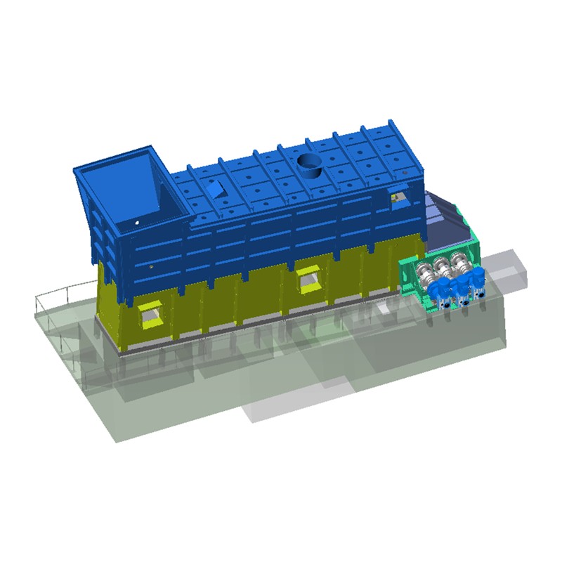
A grate cooler belongs to the family of air-quench coolers (AQC) and sits immediately downstream of the rotary kiln in every modern cement production line. It performs three jobs at the same time, and all three matter equally for plant profitability.
Quenching clinker quickly rather than letting it cool slowly has a direct quality payoff: rapid cooling locks minerals into a finer, more reactive crystal structure and produces thermal stress cracks in the clinker particles themselves, which measurably improves how easily the material grinds in the ball mill or vertical roller mill afterward. A clinker cooler that runs too slow, by contrast, produces coarser crystals, weaker cement, and higher grinding power consumption downstream — the cooler's influence extends well past its own equipment boundary.
The reciprocating grate cooler is the mainstream design used in the overwhelming majority of cement plants today, having displaced the rotary and planetary grate cooler as the industry-standard choice for kilns of virtually any size. The mechanism is straightforward once broken into its physical steps.
Hot clinker falls from the kiln outlet onto the grate bed, where it forms a material layer typically 800mm deep at the inlet, tapering to around 300mm at the outlet zone. The grate itself is made of alternating fixed and movable grate plates arranged in rows. A transmission device drives the movable plates in a horizontal reciprocating (back-and-forth) motion, and this stepping action physically pushes the clinker bed forward toward the discharge end — the same mechanism also tumbles and turns over individual clinker particles, exposing fresh surfaces to the cooling air rather than letting heat exchange happen only at the bed's top and bottom faces.
Underneath the grate, the cooler is divided into multiple compartments, each fed by its own dedicated fan with adjustable inlet vanes. Cold ambient air is forced up from below the grate, perpendicular to the direction the clinker is moving, and passes directly through the clinker bed. This cross-flow geometry — air moving vertically while material moves horizontally — is what makes the grate cooler so much more efficient than older rotary or single-cylinder designs, where the material and air share the same flow path and heat exchange is comparatively weak.
As the clinker travels the length of the cooler, it passes through three functionally distinct zones, and understanding what each zone is doing explains most cooler troubleshooting later on.
| Zone | Share of Total Cooling Air | Primary Function |
|---|---|---|
| High-temperature (inlet) | ~31% | Quench clinker, generate secondary and tertiary air |
| Medium-high temperature | ~50% | Main heat recovery zone |
| Low-temperature (outlet) | ~19% | Final cooling before discharge |
After passing through the bed, the heated air splits into functional streams: roughly 15% returns to the kiln as secondary air at about 1,050°C, roughly 22% goes to the calciner as tertiary air, and the remainder becomes excess air that is filtered through an ESP (electrostatic precipitator) or bag filter before venting or feeding a waste heat recovery boiler.
Not every grate cooler performs the same, and generation is the single biggest predictor of efficiency. Cement equipment suppliers commonly classify grate cooler technology into distinct generations, each solving the airflow-distribution weaknesses of the one before it.
| Generation | Design Feature | Typical Cooler Loss |
|---|---|---|
| 1st Generation | Conventional grate, uncontrolled air distribution | 160-130 kcal/kg |
| 2nd Generation | Air-beam / Controlled Flow Grate (CFG) | 125-100 kcal/kg |
| 3rd Generation | Stationary grate / SF cross-bar | 80-85 kcal/kg |
| 4th Generation | Cross-bar with hot-air recirculation | ~74% recovery, >70% recuperation |
The jump between generations is not cosmetic. Converting a conventional cooler to modern air-beam technology alone typically delivers 30-85 kcal/kg clinker in heat savings, alongside reduced dust circulation and lower cooling-air consumption. Fourth-generation cross-bar coolers with hot-air recirculation push recuperation efficiency past 70% by routing hot cooler discharge back into the bed rather than venting it, which is why plants running 1990s-era conventional grates almost always have retrofit potential sitting on the table.
Recuperation efficiency — the fraction of clinker sensible heat returned to the kiln system as secondary and tertiary air — is the single KPI that matters most for a grate cooler's economic performance. The published range is wide because measurement boundaries differ between studies, but the pattern below holds consistently across independent sources.
A field study on a 5,000 t/d cement plant found the heat balance splits roughly as follows: secondary and tertiary air carry away 50% of total heat, discharged exhaust air accounts for about 40%, discharged clinker sensible heat is around 9%, and radiation/surface losses make up under 1%. That 40% share sitting in exhaust air is exactly why waste heat recovery (WHR) systems have become standard investments — one documented case showed a 400 t/h line could tap approximately 30.8 MW of recoverable power from cooler exhaust alone.
The economic translation is direct and worth internalizing: each percentage point of recuperation efficiency gained is worth roughly 4-6 kcal/kg clinker in fuel savings. At typical production scale, that single percentage point commonly equates to hundreds of thousands of dollars in annual fuel cost — one documented case of a plant closing a maintenance gap recovered 4 percentage points of efficiency worth over $680,000 per year in fuel value.
Cooling air quantity is the second lever that governs both fuel savings and fan electricity cost, and the two pull in the same direction: less air per kilogram of clinker, achieved through better distribution rather than simply throttling fans, improves both numbers together.
| Parameter | Older Cooler | Modern Cooler |
|---|---|---|
| Specific cooling air | 2.5-3.1 kg air/kg clinker | 1.5-2.0 std m³/kg clinker |
| Fan power consumption | 6-7 kWh/t clinker | ~4 kWh/t clinker |
| Clinker discharge temperature | Above target | 65°C + ambient (guaranteed value) |
Reducing total air consumption from 2.0 m³/kg to 1.7 m³/kg clinker alone saves approximately 2 kWh per tonne across the production process, and every 1 kWh/t of fan power roughly corresponds to the equivalent cost of 7 kcal/kg clinker of fuel — meaning fan electricity and kiln fuel are two sides of the same efficiency equation, not separate line items. This is also why simply cranking up fan speed to force clinker temperature down is a false economy: pushing excess air beyond what the bed needs raises exhaust gas temperature and dust collector load without meaningfully raising secondary or tertiary air temperature into the kiln.
Grate cooler performance rarely fails all at once — it erodes gradually through a small set of recurring mechanical and process issues that experienced operators watch for specifically.
"Red river" describes a narrow stream of clinker that stays visibly red-hot far longer than the surrounding bed, sometimes surviving long enough to reach the clinker crusher. It happens because fine clinker particles offer far less resistance to airflow than coarse particles — in one documented example, a 2mm-versus-5mm particle size difference meant only about 17% of cooling air passed through the fine side, starving it of quenching air while the coarse side received the rest. Kilns producing dusty, fine clinker make red river almost unavoidable without a controlled-flow grate plate design specifically engineered to even out that resistance.
Wear is not uniform along the cooler length. The hot-end zone, exposed to temperatures exceeding 1,000°C and the most abrasive clinker contact, wears 3-4 times faster than the cold-end zone — meaning a single blanket inspection interval across the whole cooler simultaneously over-maintains the cold end and under-maintains the hot end. Left untracked, uneven wear opens gaps that let cooling air bypass the bed unevenly, dropping heat recovery by 3-5 percentage points without triggering any alarm, and typical plate wear progresses over a 4,000-8,000 operating-hour window that is fully predictable with condition monitoring.
Deteriorated seals at compartment joints and casing penetrations introduce uncontrolled false air — commonly 800 to 2,400 Nm³/hr — which disrupts the oxygen balance in the kiln system and raises specific heat consumption by roughly 6-14 kcal/kg clinker. Perforated or cracked grate plates create a related but more severe failure mode: hot clinker falls through into the under-grate air ducts, damaging ductwork and creating a genuine fire risk in the lower structure, with each fall-through event extending outage duration well beyond a normal planned plate swap.
Bed depth is the single most important variable for consistent cooling across the full grate width, and the target range is generally 400-600mm. Uneven distribution — often from a poorly maintained inlet spreader or breaker bar — creates hot channels on one side and overcooled dead zones on the other, degrading both clinker quality and cooling uniformity at the same time.
Most of the efficiency gap between an average cooler and a best-in-class one comes from a handful of concrete, repeatable actions rather than a single large capital project.
Most plants running a maintenance program without zone-specific, condition-based tracking are leaving 3-10 percentage points of recoverable efficiency on the table according to multiple independent assessments — meaning the highest-return project available to many cement operations right now is not a new cooler, but disciplined tracking and timely replacement of the one already installed.


 OEM/ODM High-Performance Combustion & Thermal Equipment Manufacturers
 English
 русский
 Français
 Español
 عربى
عربى